


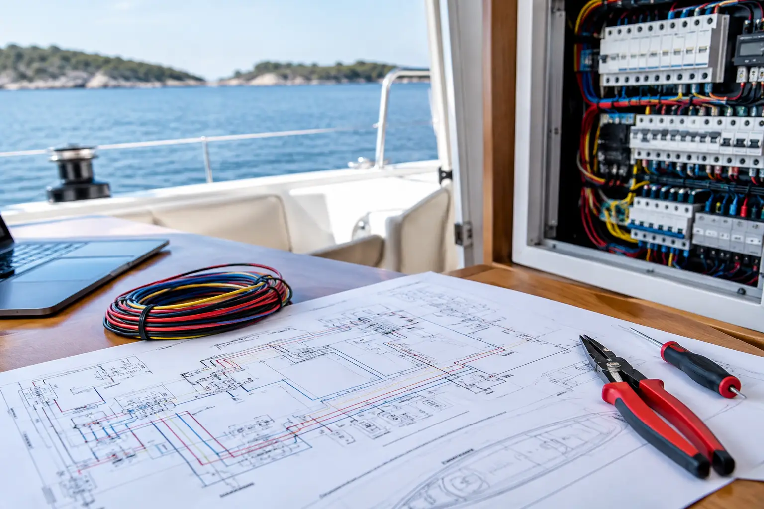
When navigation devices shut down, the winch operates slowly, or batteries fail to charge to expected capacity, the problem often lies not in a single component but in how the entire system is connected. This guide to electrical wiring diagrams on vessels assists you in understanding what the installation drawing must show, how to identify critical points, and when diagnostics should be entrusted to a professional service.
An electrical diagram is not merely an administrative document that remains in a folder after a refit. It is the technical map of your vessel: it shows where energy originates, the path it takes, what protects it, where it converts, and which consumers depend on it. On vessels with multiple energy sources, AC and DC networks, inverters, solar systems, and lithium batteries, any intervention without an accurate diagram becomes an unnecessary risk.
What a Vessel Electrical Diagram Must Show
A good diagram must allow the system to be followed in a logical sequence - from the source, through protection and distribution, to the consumers. It is not sufficient to draw only the battery, fuse, and device. It is necessary to indicate the nominal voltage, conductor cross-section, type of protection, position of switches, busbars, connection points, and ground or return conductor.
On smaller vessels, this can be a clear single-line drawing. On yachts or professional vessels, usually a set of drawings is required: separate depictions of 12 V or 24 V DC systems, 230 V AC systems, charging, engine systems, navigation networks, control and monitoring. Sometimes the layout of panels, cable labels, and connection lists are also documented. This level of documentation significantly accelerates later service interventions.
It is particularly important to distinguish between a functional diagram and an as-built drawing. The functional diagram shows the relationship between components and energy flow. The as-built drawing must show how the installation was actually constructed. If over the years a charger, inverter, bow thruster, or solar regulator was added and the drawing not updated, the documentation no longer reflects the vessel's actual condition.
Guide to Vessel Electrical Diagrams: Basic Sections
DC System - Batteries, Distribution, and Consumers
The DC system most often covers starter and service batteries, lighting, pumps, electronics, refrigerators, winches, bow thrusters, and part of the control circuits. The diagram should clearly separate the engine starting circuit from the service system and show all connections between battery banks, separators, DC-DC chargers, relays, and main switches.
For larger capacity batteries or LiFePO4 systems, it is unacceptable to consider only capacity expressed in ampere-hours. It is necessary to verify permitted charging and discharging currents, BMS capabilities, disconnection methods in case of failure, and compatibility with the alternator, charger, and inverter. Sodium-ion batteries have different operating characteristics and also require design according to specific specifications rather than simply replacing existing batteries on the principle “same size, new technology.”
The diagram must show where the main protection for each battery output is installed. A fuse is not an addition placed wherever there is space. Its rated value, breaking capacity, and position depend on conductor cross-section, expected load, and possible short-circuit current. In large battery systems, incorrectly sized or remotely located protection can have serious consequences.
AC System - Shore Connection, Generator, and Inverter
The AC system can power water heaters, air conditioning, sockets, kitchen appliances, chargers, and other 230 V equipment. Sources can be shore connections, generators, or inverters. The diagram must prevent the possibility of parallel connection of sources not intended for such and clearly show the source selector, main switches, differential protection, and overload protection.
One of the key issues is grounding and the connection of the neutral conductor with the protective conductor. The rule depends on the power source and system configuration; therefore, one must not copy solutions from another vessel. Incorrect execution can cause unwanted tripping of protection, dangerous voltages on device enclosures, or galvanic corrosion problems.
For inverters, it is necessary to check continuous and peak power, transfer switches, charging capabilities, communication with battery monitoring, and behavior when powering sensitive loads. An inverter that appears sufficiently powerful on paper may be a wrong choice if the installation, battery system, or charging cannot support its demands.
Charging and Energy Sources
The engine alternator, shore charger, solar regulator, generator, and possibly wind generator must work as a coordinated whole. The diagram shows not only where each source charges but also who manages priorities, limits current, and monitors temperature or battery condition.
A common mistake when upgrading solar panels is connecting the regulator to an existing busbar without checking voltage drop, protection, and real battery status measurement. The same applies to more powerful alternators. If the BMS interrupts charging acceptance, the alternator may lose its proper load. Therefore, modern battery systems often require DC-DC chargers, external regulators, or different charging architecture.
Monitoring, Electronics, and Communication Networks
The electrical diagram must not neglect systems that do not consume much energy but are critical for safe navigation: plotters, radar, AIS, VHF, autopilots, engine instruments, alarms, and monitoring systems. Their power supply should be clearly separated from large and variable consumers such as winches, pumps, or refrigerators when the design requires it.
Along with the power diagram, a separate depiction of communication networks—such as NMEA 2000, Ethernet, or manufacturer-specific buses—is often necessary. Power supply for the network, terminators, backbone, and connection points must be documented. Communication failures sometimes appear as single-device faults when the real cause is bad topology, voltage drop, or incorrect connection.
How to Read a Diagram During Basic Inspection
Before any work, disconnect relevant power sources and verify the actual state with measuring instruments. A switch label on the panel is not proof that a conductor is de-energized. Systems with multiple battery banks, solar charging, and inverter can have energy flowing from several directions.
When troubleshooting, follow the diagram from source to consumer. Check battery voltage, then behind the main fuse, on the busbar, behind switches, and at the device connection point. If voltage is present without load, but sharply drops when the device is switched on, the cause may be a poor connection, damaged conductor, corrosion, or insufficient cross-section — not necessarily a faulty device.
Voltage measurement is only part of diagnostics. For larger consumers, current, voltage drop under load, and connection temperature must also be measured. Heating of the connection, discoloration of insulation, or smell of overheated plastic require immediate inspection. A temporary “solution” with a larger fuse is not a repair but an increased risk.
When the Existing Diagram Is Not Sufficient
The diagram is outdated if it does not show the actual installed equipment, lacks protection and conductor cross-section labels, or if during previous interventions parallel conductors and temporary connections were added. This is often discovered only during refits, used boat purchases, or recurring faults which various technicians attempt to fix by replacing components.
The correct procedure then is a technical inspection of the existing condition. Batteries, chargers, energy sources, distribution panels, cable routes, connections, protective elements, and actual loads are inspected. Following this, documentation of the as-found condition and an upgrade project that will not compromise existing systems may be created.
For larger interventions such as transition to LiFePO4, installation of an inverter, solar power plant, electric propulsion, or a more powerful bow thruster, designing before equipment procurement reduces compromises. Not every component is compatible with the existing installation, and not every technically correct system is equally suitable for charter, private cruising, or long-term anchorage.
From Drawing to Reliable Operation
A quality vessel electrical diagram is as valuable as it corresponds to the actual installation. Therefore, design should be connected with professional installation, proper conductor labeling, device configuration, measurements, and commissioning. After interventions, documentation should be updated so that the captain, owner, and future service personnel have a reliable starting point.
UnLucky conducts inspections of existing installations, technical compatibility checks, design, installation and integration of energy and electronic systems, diagnostics, and preventive maintenance. If your vessel has unclear, incomplete, or outdated electrical documentation, send an inquiry with basic vessel data, existing equipment, and planned upgrades. A reliable system does not start with luck but with verified condition and clearly drawn path of every connection.