
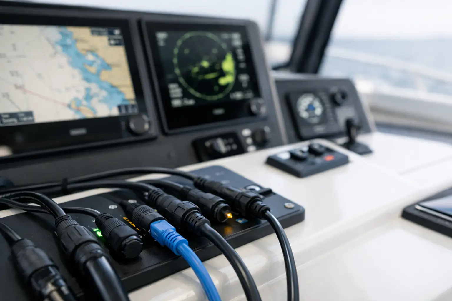
When a plotter displays incorrect positioning, an autopilot does not follow the set route, or a VHF radio does not receive GPS data for a DSC call, the cause is often not a malfunction of an individual device. The problem usually lies in how devices exchange data with each other. This guide to the NMEA network explains how the system functions, what to check before upgrading, and why the network should be considered as a whole rather than a collection of separately connected devices.
Onboard vessels, the NMEA network connects navigation electronics, sensors, propulsion, and monitoring systems. It enables data about position, heading, depth, wind, speed, engine status, or battery condition to reach devices that need to use it. A properly designed network increases clarity and functionality. Poorly executed networks can cause intermittent errors that appear just when navigational data is most critical.
What the NMEA Network Actually Transmits
NMEA is a communication standard for exchanging data among marine devices. Rather than each device operating in isolation, the network allows shared use of information. A GPS receiver can send position data to the plotter, VHF radio station, AIS device, and monitoring system. A heading sensor can send data to the autopilot, radar, and navigation computer.
It is important to distinguish the network itself from device power supply. The NMEA cable can supply bus power, but it is not a substitute for properly executed electrical circuits, fuses, conductor sizing, and protection against voltage drops. Navigation and electrical installations must be designed together, especially on large yachts, refits, and vessels with multiple power sources.
Data traveling through the network can be simple, such as GPS position and time, or more complex, like engine parameters, tank statuses, fuel consumption, inverter operation, and battery system condition. However, the fact that two devices have an NMEA port does not automatically mean they will share all expected data.
NMEA 0183 and NMEA 2000 Are Not the Same
Many vessels, especially those upgraded gradually, have both standards. NMEA 0183 is an older serial communication method. It usually connects one data source to one or a limited number of receivers. It requires proper wiring for sending and receiving lines, and transmission speeds and message formats may vary between devices.
NMEA 2000 uses a common bus, or backbone, to which devices connect via T-connectors and separate drop cables. It allows a larger number of devices to exchange data simultaneously and is now the standard solution for most new navigation, engine, and monitoring systems.
NMEA 2000 is not only more convenient because it reduces the number of individual data connections. Its advantage lies also in more structured data exchange. Still, the network has limitations in length, current consumption, number of devices, and communication load. When performing extensive refits, one should not assume the existing backbone will accommodate all new components without technical verification.
When a Converter Is Needed
NMEA 0183 and NMEA 2000 cannot be connected with a simple cable. If an older device with NMEA 0183 needs to exchange data with a newer NMEA 2000 network, an appropriate gateway or converter is required. Merely verifying the physical connection is insufficient.
The converter must support the specific data you intend to transfer. For example, GPS position may pass bidirectionally, but specific messages for autopilot, AIS, or engine control will not be available without proper configuration. Therefore, compatibility is verified by device documentation, software version, and desired data flow.
Structure of the NMEA 2000 Network
A reliable NMEA 2000 installation has a clear structure. The backbone is the main bus running through the vessel, and each device connects with a short drop cable via a T-connector. Terminators must be installed at both ends of the backbone. The network power supply is introduced at a designated location through a separately protected circuit.
Common mistakes occur when expanding the network without a plan. Someone adds a T-connector at a convenient point, another device receives power through an improvised adapter, and existing termination remains hidden behind the instrument panel. The system may continue to operate but becomes sensitive to interruptions, voltage drops, and occasional device disconnections from the network.
Terminators are not optional equipment installed only if there is room. They electrically terminate the bus and prevent signal reflections. Without two correctly placed terminators, communication can become unstable. Conversely, having more than two terminators may also cause problems.
Power Supply, Fuses, and Voltage Drop
The NMEA 2000 network requires a stable power supply with appropriate voltage and capacity. The backbone power should not be planned randomly, especially when the network includes several displays, engine gateway devices, sensors, digital switching modules, and battery monitoring systems.
Every major consumer must have its own properly sized power supply according to the manufacturer’s instructions. The network cable is not intended to replace main feeding lines for the plotter, radar, or autopilot. Separating the data network from power design reduces interference and eases future diagnostics.
On vessels equipped with LiFePO4 batteries, inverters, DC-DC chargers, or powerful bow thrusters, special attention must be paid to grounding, cable routing, and possible electromagnetic interference. NMEA issues may appear only when a large consumer is switched on, though the actual cause is a voltage drop or inadequately executed return conductor.
Compatibility Is Not Only a Matter of Connectors
Connectors from different manufacturers may look similar or connect via suitable adapters. This does not guarantee functional compatibility. Devices must understand the same messages and have correctly defined data sources.
A vessel may have multiple sources of GPS position, heading, depth, or speed. If the plotter uses one GPS, VHF another, and autopilot a third heading source, the crew may receive conflicting data. This is especially critical when integrating autopilot and radar, where the quality of heading source influences radar overlay functions, stabilization, and route tracking.
It is necessary to establish which device will be the primary source for each data type, then configure priorities on the network. Sometimes it is correct to keep an existing sensor. In other cases, a new multifunction display cannot compensate for a lack of a quality heading, depth, or wind sensor.
How to Identify an Issue in the NMEA Network
Intermittent data loss, devices not visible in the network component list, illogical depth or heading values, and autopilot refusing navigation commands are typical signs that the system requires diagnosis. The fault may not be on the device showing the error.
Professional diagnostics start with reviewing the network topology: the position of the backbone, T-connectors, terminators, power sources, and all connections. Then voltage and continuity are checked, network devices and their software parameters are examined, and messages sent and received by devices are analyzed.
Common causes include connectors damaged by moisture and salt, excessively long or improperly installed drop cables, and devices that change data source settings after firmware updates. Without systematic checks, it is easy to replace a functioning device while the real problem remains in the installation.
Planning the Network Before Installation or Refit
Before purchasing a new plotter, autopilot, AIS, VHF radio, or battery monitor, it is essential to define what the system must accomplish. Should the VHF automatically receive GPS position? Should the autopilot follow routes from the plotter? Should the status of batteries, tanks, and engines be displayed on a single screen? Will data be monitored remotely?
The answers determine network architecture, the need for gateway devices, sensor locations, number of connections, and reserves for future expansion. When refitting, it is equally important to inspect existing cables, penetrations, distribution panels, and the space behind the helm. New electronics installed on a limited or disorderly existing infrastructure rarely deliver the expected result.
Professional installation and integration include technical compatibility checks, topology design, neat cable labeling, connection protection, data source configuration, and commissioning. Final verification must be performed under real operating conditions with the engine running, chargers, radar, communication equipment, and other relevant consumers active.
If you are planning new navigation equipment, expanding monitoring of vessel systems, or diagnosing existing issues, send an inquiry with a list of equipment and a description of your vessel usage. At UnLucky, we assess the actual state of the installation before recommending solutions, because reliable marine electronics do not depend on luck. Because Luck Has Nothing to Do With It.