


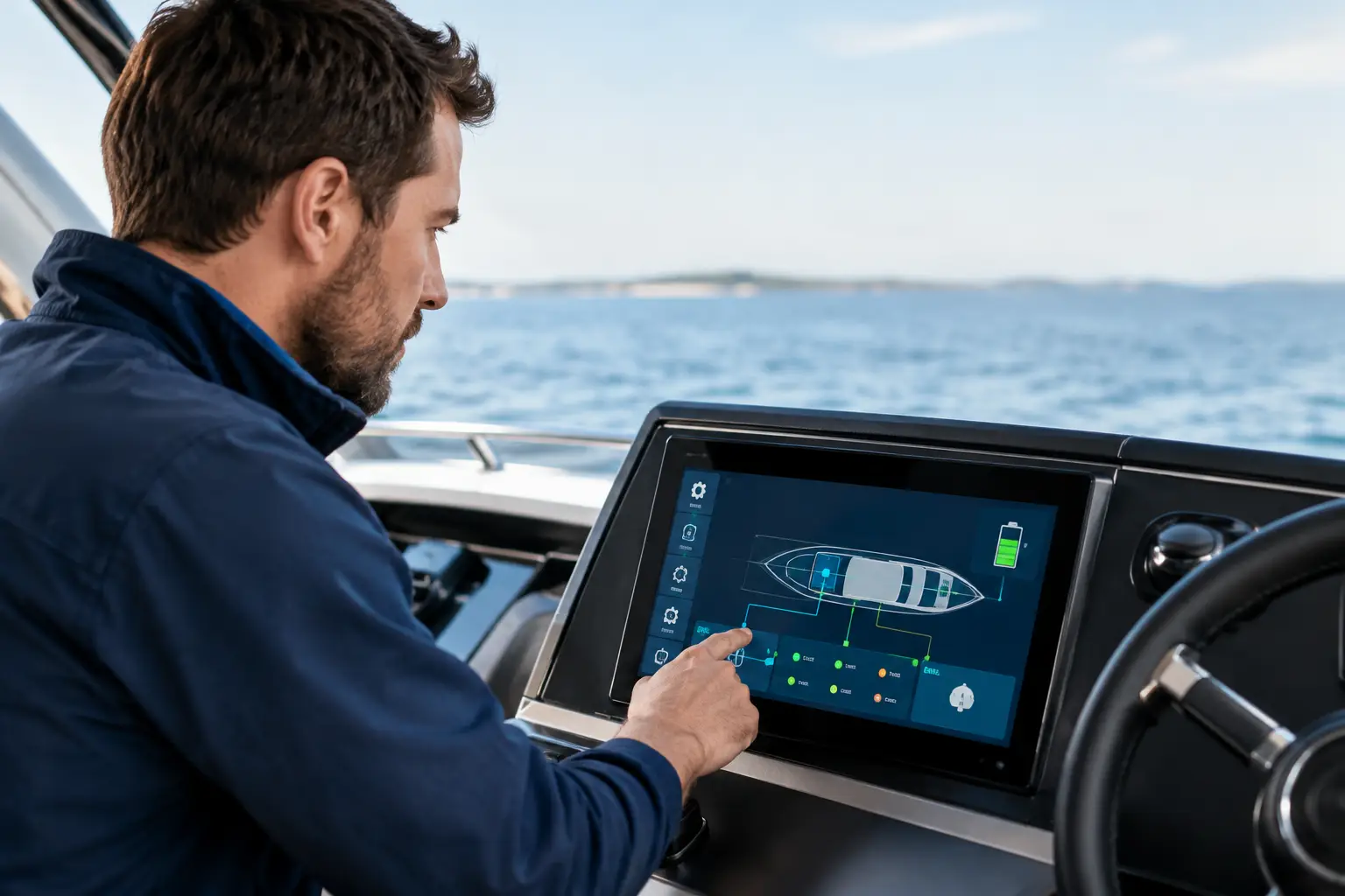
The battery system may display 100% charge on the screen while one cell operates outside the allowed voltage range, the temperature sensor does not send data, or the charger uses an incorrect profile. Therefore, a smart BMS test is not just a formality after LiFePO4 battery installation but a technical verification that confirms the actual system status before setting sail.
Onboard, the BMS manages the limits within which the battery can safely operate. It monitors individual cell voltages, charging and discharging currents, temperature, and depending on the design, controls contactors or sends data to other devices. A smart BMS additionally enables communication via Bluetooth, CAN, NMEA 2000 network, or dedicated monitoring systems. However, mere data availability does not guarantee that parameters are set correctly or that all system parts respond as required.
What a Smart BMS Test Must Confirm
A proper test starts from the entire power system, not just from the mobile application. The BMS is connected to the battery pack, shore chargers, alternator, DC-DC charger, solar regulator, inverter, and significant DC consumers. A configuration error in one device can cause unwanted battery shutdown or shorten its service life.
The first step is verifying basic data the BMS reads. The total pack voltage must correspond to the actual charge state, and the cell voltage deviation should be within limits suitable for the specific battery and its condition. Larger deviations do not automatically signify a fault. They may appear after long standby, incomplete balancing, or uneven operation of parallel-connected modules. Still, the cause should be determined before the vessel embarks on a longer voyage.
Temperature data is checked similarly. A BMS that does not correctly read temperature cannot reliably stop charging at too low or too high temperatures. In LiFePO4 technology, charging at low temperatures is especially critical. If the battery is placed in a space that cools in winter or overheats in summer, temperature protection must be properly set and genuinely tested, not just enabled in the application menu.
Charging is Verified Under Real Conditions
Testing should cover every charging source your vessel uses. Shore chargers, solar regulators, alternators via DC-DC chargers, and generators may have different voltage profiles and operating modes. Their settings must correspond to battery pack specifications and BMS capabilities.
During verification, it is observed whether the system reaches the set charging voltage, what current is present at each phase, and whether it reduces correctly approaching full capacity. It is also checked how the BMS reacts when approaching the cell’s upper voltage limit. If protection activates too early, the battery’s usable capacity may be unnecessarily limited. If it activates too late, cells are exposed to overloading.
Special attention is required for alternator charging. Direct connection of a large LiFePO4 pack to an alternator without proper regulation can overload the alternator beyond its design capacity. A DC-DC charger, external regulator, or other appropriate solution must limit the current and coordinate the charging source operation with the battery system. Testing confirms behavior at engine start, changes in RPM, and system heating.
Discharging Reveals Actual System Capability
The battery may appear normal while powering lighting and small loads, but problems become visible only under higher load. An inverter, bow thruster, windlass, cooker, air conditioner, or electric propulsion can demand very high currents. Load testing demonstrates whether the voltage falls excessively, cables and connections heat up, and if the BMS operates within declared continuous and peak current limits.
There is no universal setting here. A 200 A BMS may suffice for a service bank on a sailing yacht but be insufficient for systems with larger inverters or devices with pronounced starting current. Conversely, dimensioning solely by the maximum possible load without analyzing cables, fuses, busbars, and charging sources does not solve the problem. The system must be designed as a whole.
If the BMS uses contactors, their behavior is also tested during charge or discharge interruption. The interruption must be predictable and must not leave critical boat systems without power due to thoughtless circuit division. Navigation equipment, communications, bilge pumps, and safety consumers require careful planning of power supply and protection.
BMS Communication with Monitoring Systems
A smart BMS has full value only when information to the user and other devices is accurate and timely. The Bluetooth app is practical for local diagnostics but is not a substitute for integrated onboard monitoring. The captain or crew must be able to check the battery status without opening the compartment and connecting a phone every time a warning appears.
When integrated via CAN or NMEA 2000 networks, it is verified whether correct data about voltage, current, state of charge, temperature, and alarms is displayed. It is also essential that chargers or inverters, if supporting communication with BMS, properly receive commands to limit or stop operation. An uncoordinated communication protocol can lead to situations where the display shows data but the charger does not react to BMS’s protective requests.
Alarms must also be tested. Warnings for low voltage, high temperature, excessive current, or communication errors must be clearly visible and understandable. An alarm buried deep within an app is insufficient for a system that the vessel’s autonomy depends on. Larger yachts can connect alarms to a central monitoring system, while on smaller vessels, local visual or audible alerts are typically appropriate. The choice depends on usage mode and existing automation level.
Common Failures After Battery Installation
Problems often do not arise from the battery itself but from incomplete integration. The BMS can be of high quality, but safety has no meaning if cables are improperly sized, fuses are chosen without coordination with current limits, or the current sensor is placed so it does not measure all power flows.
Incorrect state-of-charge parameters are also frequent. The BMS or battery monitor must know the actual capacity, charging efficiency, and the initial reference point. Without proper synchronization, the charge percentage becomes unreliable over time. This is especially troublesome at anchor where residual autonomy estimation determines operation of refrigerators, watermakers, inverters, and other consumers.
After any significant system change, retesting is recommended. Adding a solar array, inverter replacement, installing a larger charger, or changing alternator charging alters operating conditions for the entire battery bank. Preventive maintenance is then significantly more favorable and safer than diagnostics after system shutdown during navigation.
Professional Inspection Before Season and Longer Voyages
Smart BMS testing requires measurement, configuration control, and understanding relationships among devices. It is not enough to confirm the battery charges. It is necessary to check charging and discharging limits, protection behavior, operation under load, connection quality, and data transmission to vessel monitoring.
UnLucky conducts an existing power system review, technical compatibility verification, diagnostics of BMS and connected devices, and if needed, configuration and commissioning. If planning a new LiFePO4 or sodium-ion installation, design, proper sizing, and post-installation system verification are equally important.
Send an inquiry with vessel data, battery, BMS, charging sources, and existing consumers. A clearly tested system does not rely on assumptions. Because Luck Has Nothing to Do With It.