


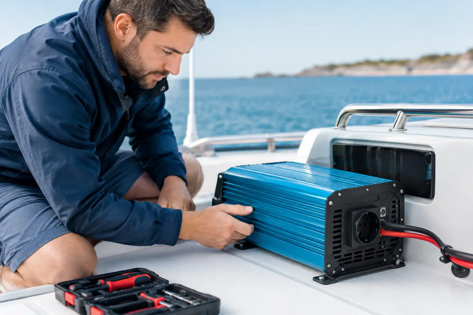
An inverter that powers on without alarms is not necessarily fault-free. Testing marine inverters must demonstrate how the device performs under actual load, how it responds to battery voltage changes, and how well it integrates with the rest of the AC and DC system. It is precisely under these conditions that problems often appear, remaining hidden while docked but causing serious autonomy interruptions during sailing, anchoring, or operation without shore power.
A marine inverter converts direct current energy from the battery system—commonly 12 V, 24 V, or 48 V—into an alternating voltage of 230 V. It powers devices such as outlets, portable device chargers, kitchen appliances, tools, audiovisual equipment, and, depending on the design, certain larger consumers. If it is an inverter-charger, its role is broader: it manages battery charging from shore power or generators and often participates in switching power sources.
Therefore, testing must not be only a brief voltage check at the outlet. The device, battery system, conductors, protections, transfer functions, and actual consumers must be verified as one technical unit.
Why Marine Inverter Testing Should Be Done Under Load
The inverter’s display may show 230 V, while in practice the system experiences a voltage drop on the DC side. This occurs when cables are undersized, too long, poorly connected, or when terminals have oxidized and heat up. Such faults may go unnoticed at low load. When a higher-power appliance is activated, the inverter may report low battery voltage, enter protection mode, or shut down completely.
The same applies to batteries. A degraded lead-acid battery, improperly configured LiFePO4 bank, or a battery system limited by the BMS may appear to have acceptable voltage. However, under heavier discharge, their available capacity and current delivery capability may be significantly less than expected. The inverter is then not the cause but the first device to indicate the problem.
Testing under controlled load allows observation of inverter input voltage, input current, output voltage, and connection temperatures. The goal is not to stress the system to the limit without reason, but to confirm that the designed power matches your vessel’s usage.
Rated Power Is Not the Whole Story
A 3000 W inverter does not automatically mean it can continuously and safely supply every 3000 W load. Continuous power, short-term peak power, and the starting current of devices with electric motors or compressors must be distinguished. An appliance with moderate rated power may require multiple times that power at startup.
On the DC side, the numbers become even more demanding. An inverter delivering approximately 2000 W at 12 V can draw over 180 A from batteries considering conversion losses. This requires appropriately sized cables, quality terminals, correctly rated fuses, a main switch, and batteries capable of safely handling such currents. At 24 V or 48 V systems, currents are lower for the same output power, often a key factor when designing larger energy systems.
What a Professional Inverter Inspection Includes
A thorough inspection starts with understanding the system, not just measuring one outlet. First, inverter type, rated power, output waveform, device age, and how it is connected to the vessel's AC installation are determined. For sensitive electronics, chargers, induction devices, and motors, a pure sine wave output is generally expected. Modified sine wave may be acceptable for limited uses but can cause noise, overheating, or improper function of some consumers.
Next, the DC installation is checked. Cables, routes, mechanical protection, fuses, switches, busbars, and battery connections are inspected. Any sign of heating, insulation discoloration, loose connections, or unsuitable fuses must be addressed before applying higher loads. Fuses protect cables and installations, not serve as a means to conceal improper cable sizing.
On the AC side, power source distribution is verified. The inverter, shore power, and generator must be connected to prevent undesired back-feed to another source. Source switching must be technically correctly implemented, and protective conductor, neutral conductor, and protective switches must align with system operation. Improvised later connections in this area can create real safety risks.
During functional testing, the inverter’s behavior when progressively switching on consumers is observed. Output voltage and frequency stability is measured, heating monitored, and alarms for low voltage, overload, and overheating are checked. If the inverter communicates with battery monitors, BMS, or supervisory systems, data accuracy and system response to charging and discharging limits are also verified.
Specifics of Inverter-Chargers and Lithium Batteries
An inverter-charger should not be viewed as a standalone device. Its settings must match battery chemistry, bank capacity, available shore current, and generator power. Improperly set charging current can unnecessarily stress marina installations, trigger generator protections, or cause equipment to overheat.
For LiFePO4 systems, it’s especially important to coordinate the inverter-charger with the BMS. The BMS may disconnect batteries when current, voltage, or temperature limits are exceeded. If the inverter lacks proper configured behavior after such disconnection, it may shut down under load or generate numerous alarms. The solution is not bypassing the BMS but properly designing limits and communication between components.
It is also necessary to verify if the system can survive sudden battery power loss without damaging sensitive devices. This depends on the system architecture, presence of other charging sources, DC-DC chargers, solar controllers, and how consumers are distributed across circuits.
Idle Consumption and Actual Autonomy
Inverters consume energy even when no significant AC load is connected. This idle consumption may be low but becomes relevant during multi-day anchoring, especially on smaller battery banks. Functions like sleep mode or automatic wake-up can help, but their behavior must be checked with real consumers.
Autonomy is not just estimated by dividing battery capacity by device power. Allowed depth of discharge, inverter losses, simultaneous DC loads, solar production, possibility of engine or generator charging, and crew habits must be considered. An owner who occasionally uses a coffee machine requires a different system than a charter vessel that daily powers several cabins, kitchen appliances, and crew work equipment.
When Urgent Servicing Is Needed
Occasional inverter alarms are not always signs of device failure but should not be ignored. Inspection is justified if the inverter shuts down under loads it previously handled, if there is a smell of heated plastic or unusually warm cables, if battery voltage drops suddenly, or if switching between shore, generator, and inverter is unpredictable.
Equally important after battery replacement, LiFePO4 upgrades, solar panel installations, addition of larger consumers, or changes in vessel purpose. Such changes may alter current loads and logic of existing systems. A component suitable before refit may be unsuitable afterward.
Technical inspection can determine if the current inverter needs servicing, different configuration, or replacement with a device of appropriate power and functionality. Sometimes problems are solved by correcting installations, replacing connections, or optimizing settings without replacing the device.
For reliable operation, do not rely on the assumption the system works because it worked last season. Request diagnostics, load testing, and technical verification of inverter compatibility with your batteries and consumers. Because Luck Has Nothing to Do With It.