


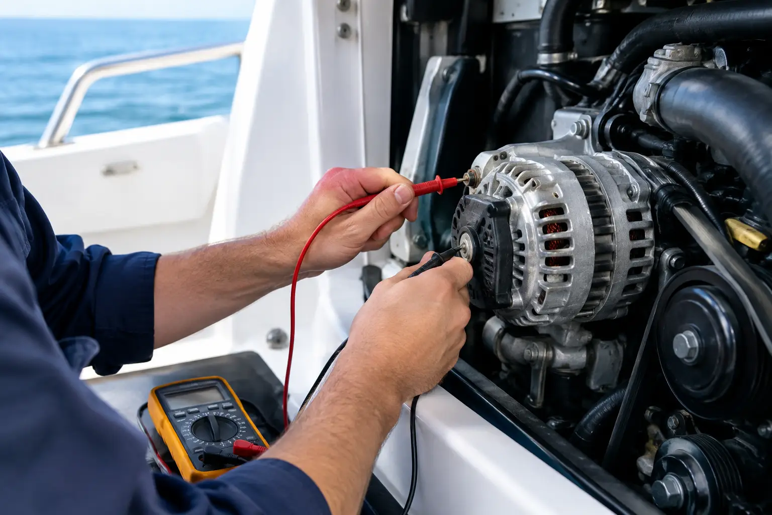
An alternator that shows charging on the instrument may still cause drained batteries, cable overheating, or unreliable consumer operation. Therefore, the question of how to test a marine alternator is not just about a single voltage reading. Proper diagnostics must include mechanical drive, battery bank, cable connections, charge regulator, and actual system load.
On a vessel, the alternator is part of an integrated energy system. Its operation directly affects availability of navigation, communication, refrigeration, pumps, bow thruster, and other key consumers. It is especially important to check the system before the season, after prolonged lay-up, installation of LiFePO4 batteries, or recurring service bank discharges.
Before measuring, verify what the alternator actually charges
First, determine the basic system architecture. Is it a 12 V or 24 V installation? Does the alternator charge only the starter battery, the service bank, or is it connected via a splitter, automatic relay, DC-DC charger, or external regulator? Without this information, measurement results may be misinterpreted.
In a classic 12-volt system, charging voltage typically ranges roughly between 13.8 and 14.6 V under engine operation. In a 24-volt system, expected values are approximately double. However, this is not a universal rule. Temperature-compensated regulators, smart alternators, and charging profiles for AGM, gel, or lithium batteries may deliberately vary voltage through different charging phases.
Also check the rated alternator current, cross-section and length of output cable, and battery condition. A 120 A alternator will not necessarily deliver 120 A at all times. Output current depends on engine speed, alternator temperature, battery state of charge, regulator settings, and limitations of the rest of the installation.
Safety before testing the marine alternator
Measurements are conducted while the engine runs, near belts, pulleys, and hot engine parts. Ensure the engine compartment is ventilated, wear close-fitting clothes, and keep hands, instruments, and measuring leads away from moving parts. If testing on a gasoline-powered vessel, always perform prescribed ventilation of the engine space before starting the engine.
A digital multimeter and DC current clamp are fundamental tools for inspection. Use the correct measurement range and measure on clean metal contacts, not over oxidized lugs or bolts. For larger systems, a thermal camera is also useful, as overheated connections often reveal resistance that voltage alone does not show.
Never disconnect the battery while the engine is running to check if the alternator works. This outdated procedure can cause a large voltage spike and damage the regulator, instruments, navigation electronics, or other sensitive equipment. Do not rely on sparking when touching cables as an indicator of functionality either.
1. Visual and mechanical inspection
Turn off the engine before electrical measurements and inspect the alternator. Check if the housing is firmly secured, signs of corrosion, oil, water, or overheating, and if B+ and ground terminals are clean and mechanically secure. Greenish or white oxidation on copper connections increases resistance and can significantly reduce charging efficiency.
Inspect the drive belt. It must not be cracked, greasy, glassy shiny, or too loose. Belt slip is often recognized by fine black dust around pulleys, occasional squealing, or weaker charging under higher load. For multiple belts, all must be equally worn and properly tensioned.
Also check the ground cable between the engine, alternator, batteries, and common bus bar. A poor ground connection can cause symptoms almost identical to alternator fault: low charging voltage, unstable readings, heating of connections, and occasional operational interruptions.
2. Measure battery voltage with engine off
With the engine off and no active charger, measure the voltage directly on the battery terminals. After resting, a fully charged lead-acid 12 V battery usually shows roughly 12.6 to 12.8 V. A lower voltage may indicate a partially discharged or worn battery, but does not in itself confirm an alternator fault.
If the battery was just charged, surface charge may temporarily raise the reading. Turn on a moderate load for a few minutes or wait for the battery to stabilize. For LiFePO4 batteries, resting voltage is not sufficiently precise an indicator of state of charge, so rely on the BMS, battery monitor, and charge current data.
This initial measurement serves as a reference. When the engine starts, voltage on the same battery must change meaningfully if the alternator and charge path work correctly.
3. Check charging voltage during engine operation
Start the engine and let it run at idle. Connect the multimeter directly to the poles of the battery the alternator is meant to charge. After a few moments, read the voltage, then repeat the measurement at higher engine speeds, according to the engine manufacturer's guidelines and safe operating conditions.
If voltage does not rise above battery resting voltage, causes may include alternator or regulator fault, excitation wire break, blown fuse, faulty charge relay, belt slip, or wiring interruption. If voltage rises but remains too low, determine whether there is a problem with alternator capacity, voltage drop in cables, or system control logic.
Overly high voltage is also a serious sign. Continuous charging above the manufacturer’s recommended voltage can cause increased electrolyte evaporation in lead batteries, overheating, activation of BMS protection, or shortening of the battery bank lifespan. Do not assume higher voltage automatically means better charging.
4. Test the alternator under real load
Voltage without load is not sufficient proof the alternator can sustain the system. Turn on larger DC consumers intended for operation during navigation, such as refrigerator, lighting, pumps, or inverter, respecting your installation’s limits. Observe battery voltage and, if you have current clamps, the current on the alternator’s B+ output cable.
A proper system should maintain charging voltage according to the selected profile, and the alternator should provide a meaningful increase in current when the battery bank is partially discharged. If voltage drops sharply under load, causes may be an underpowered alternator, thermal limitation of the regulator, poor connection, worn batteries, or undersized cable.
During testing, do not deliberately overload the alternator. Prolonged operation at maximum current can overheat it, especially in an enclosed engine compartment. An alternator rated for high output current often cannot sustain that value continuously at temperatures prevailing on the vessel.
5. Measure voltage drop on positive and ground
Voltage drop reveals problems that measurement solely on the battery can easily conceal. While the alternator charges under load, measure voltage between the alternator’s B+ terminal and the positive battery pole. Then measure between the alternator housing or its ground and the battery negative pole.
Values should be low. As a practical rule, voltage drop on each conductor should not exceed a few tenths of a volt under significant current. A higher drop indicates oxidized connection, undersized cable cross-section, poor ground connection, corroded battery switch, fuse, or busbar with excessive transition resistance.
Such a fault is not only a charging problem. A connection with high resistance converts energy into heat, which can damage insulation, terminals, and surrounding components. Therefore, inspection also includes temperature checks of cables, lugs, fuses, and switches after operation under load.
When the alternator is not the main cause of problems
A battery with high internal resistance can accept very little current and create the impression the alternator does not work. Conversely, a deeply discharged or damaged battery may demand prolonged high current and overload the alternator. In LiFePO4 battery systems, it is especially important to verify if alternator current control and adequate overheating protection exist.
Problems often appear after partial system upgrades. Installing a larger battery bank, inverter, or smart charger without checking alternator, regulator, cable, and protective element compatibility can change the entire operating regime. An alternator suited for a standard starter battery may not be appropriate for fast charging a large service bank.
When to call service for system diagnostics
If the alternator does not charge, overcharges, produces unusual noise, smells burning, or cables and connections heat up, do not continue experimental measurements during navigation. System diagnostics covering alternator, regulator, batteries, protection, cable routes, and actual consumption profile are required.
UnLucky performs technical compatibility checks, charging diagnostics, and installation and integration of alternators, external regulators, DC-DC chargers, and battery systems. After inspection, it is possible to clearly determine if existing alternator requires servicing, regulator replacement, connection refurbishment, or design of a safer charging system for how you use your vessel.
Send an inquiry with information about the engine, alternator, battery type and capacity, and measured voltages. Accurate diagnostics before breakdown at anchor or during navigation is always a better choice - Because Luck Has Nothing to Do With It.