


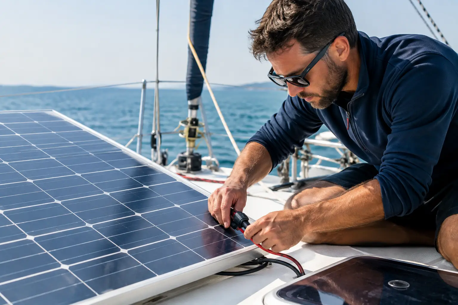
A solar panel mechanically attached to a bimini or cabin roof is not yet a solar system. The question of how to connect solar panels on a vessel begins with assessing consumption, battery condition, and existing charging, and ends only when the system is properly configured and tested under load. Incorrect cable sizing, a regulator without proper protection, or poor connections in a humid environment can reduce production, damage equipment, or create serious electrical hazards.
In the Adriatic, solar energy can significantly increase the autonomy of a sailboat, motorboat, or catamaran. However, performance depends not only on the panel's nominal power. It is influenced by shadows from the mast and antennas, panel positioning, temperature, battery chemistry, consumption profile, and the way the alternator, shore charger, and generator are already connected to the system.
First, determine what the solar system should cover
The solar system should be designed based on actual daily consumption, not the desired number of panels. On a vessel with basic consumers, this might include the refrigerator, lighting, pumps, device chargers, and instruments. On larger vessels, consumption is significantly increased by autopilots, radar, communication equipment, inverters, freezers, stabilization, electric toilets, and monitoring systems.
Consumption is calculated in ampere-hours or watt-hours over a typical day at anchor. One must distinguish summer cruising from marina operation, frequent short motor passages, and multi-day stays without shore connection. Solar can reduce the need for running generators or engines for charging, but is rarely the sole energy source on vessels with higher hotel loads.
It is equally important to identify your battery type. Lead-acid, AGM, gel, LiFePO4, and sodium-ion batteries have different charging requirements, voltage thresholds, and current charging tolerances. The charge controller must be matched to the battery chemistry and, for lithium systems, to the BMS as well as the overall energy distribution architecture.
How to Connect Solar Panels: Basic Architecture
In a properly designed DC system, energy flows predictably: solar panels generate direct current, the charge controller adjusts voltage and current to the battery system, and batteries deliver energy to consumers through protected distribution. Between these elements lie appropriately sized cables, fuses, switches, busbars, and quality connections.
The most common arrangement is panel - DC protection and disconnect ability - MPPT controller - fuse to battery - battery busbar. The controller is generally installed as close as possible to the batteries, respecting manufacturer instructions and ventilation. This reduces voltage drop on the charger side and allows the controller to more accurately monitor the actual battery voltage.
The connection from the controller to the battery must be protected by a fuse that protects the cable, not just the device. Protection must be installed as close as possible to the energy source, that is, the battery busbar, according to the system design. On the panel side, disconnection points are also provided for servicing and diagnostics, and with multiple parallel strings, individual string fuses may be necessary.
It is not sufficient to connect positive and negative leads according to insulation color code alone. On older vessels or after multiple modifications, markings are often unreliable. Before any work, polarity, existing conductor condition, voltage drop, and grounding or return conductor implementation must be verified by measurement.
Series or Parallel Panel Connection
Panels can be connected in series, parallel, or a combination. Series connection increases the array voltage while current remains approximately equal to that of a single panel. This can reduce losses on longer runs and suits controllers with sufficiently high allowed input voltage.
Parallel connection maintains approximately the same voltage but increases current. It is often practical when panels are differently shaded but requires larger conductor cross-sections and properly implemented protection for each string. Under partial shading, system behavior also depends on panel construction, bypass diodes, and MPPT controller algorithms.
There is no universal answer as to which connection is better. Two identical panels on the same roof face different conditions than flexible panels distributed on a bimini, where parts of the surface are shaded by sails, radar, or dinghies during the day. Therefore, before selection, panel operating voltage, open-circuit voltage at low temperatures, maximum allowed controller current, and actual cable routes are checked.
Why MPPT Controllers Are the Most Common Choice
The MPPT controller tracks the maximum power point of the panels and converts the higher input voltage of the panels to the charging voltage required by the batteries. On vessels, it is often more suitable than a PWM controller, especially with larger panels, series connections, and variable illumination conditions.
However, MPPT is not automatically the correct solution if selected improperly. The controller must withstand the maximum open-circuit voltage of the solar array including temperature margin and the expected output current to the battery. It must also have a charging profile appropriate for the battery bank. For LiFePO4 systems, communication methods or control signaling with the BMS are verified, especially when the BMS can limit or interrupt charging.
If the vessel has multiple charging sources, the solar controller should not be considered in isolation. The alternator with external regulator, shore charger, generator, and DC-DC charger must have harmonized voltage settings. Otherwise, one source may unnecessarily take over charging, another may frequently toggle on and off, and batteries will not operate in the intended regime.
Cables, Connectors, and Protection in a Marine Environment
The marine environment is unforgiving of poor connections. UV radiation, salt, vibrations, condensation, and high temperatures accelerate component aging. Cables for the solar array must be suitable for outdoor use and UV exposure, while cables within the vessel must comply with marine installation standards, be properly routed, secured, and abrasion-protected.
Cable cross-section is determined by current, run length, allowable voltage drop, and installation method. Undersized wiring not only reduces yield but causes heating, increases losses, and can impair proper battery charging. Special attention is given to deck penetrations, bulkheads, and technical spaces. These must be watertight, mechanically relieved, and designed so water does not follow cables into the vessel interior.
Connectors must be compatible, properly crimped, and accessible for inspection. Joining different connector types with adapters of uncertain quality increases potential weak points. All conductors should have appropriate terminations, labeling, and neat connections on busbars. This greatly facilitates diagnostics and maintenance later.
Mechanical Installation Affects Electrical Outcome
A panel may have a correct electrical connection but still provide poor yield due to poor placement. Rigid panels on mounts generally have better cooling and higher performance than panels fully glued to heated surfaces. Flexible panels can be justified when mass, curved surfaces, or access constraints are decisive but require realistic appraisal of durability and substrate temperature.
Before drilling the deck or cabin roof, construction, cable routing, possible water ingress, and impact on access to service openings are assessed. On a sailboat, the operation of sails, sheets, and bimini structure must be considered. On a motorboat, shadows from radar, dinghy carriers, and superstructures must be anticipated. Any panel occasionally shaded should be regarded as part of total production, not only by its nameplate data.
Commissioning Is Not a Formality
After installation, measurements and configuration must be conducted. Polarities, panel voltage before connection, battery bank voltage, fuses, voltage drops, controller settings, and system behavior during charging are inspected. In integrated onboard systems, it is useful to display solar yield and battery status on the monitoring system so the crew can promptly detect deviations.
Preventive inspection includes checking connection tightness, signs of corrosion, condition of cable glands, panel cleanliness, and controller data. If production suddenly drops, the cause is not necessarily panel failure. Common causes include shading, oxidized connections, blown fuses, damaged cables, incorrect configuration, or batteries no longer accepting charge at expected capacity.
For the vessel owner, the most important is that the solar system is a predictable part of the energy whole, not a separate add-on installed without compatibility checks. UnLucky can review the existing condition, design the system, select appropriate components, perform installation and integration, and conduct commissioning. Send an inquiry with vessel, battery, existing charging sources, and expected consumption details. Because Luck Has Nothing to Do With It.