


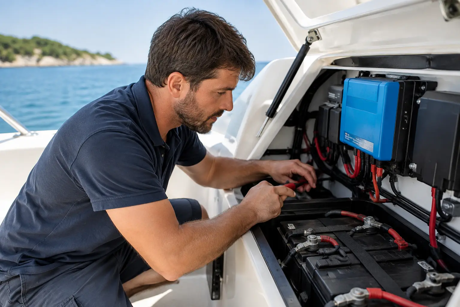
Undercharged service batteries are often only noticed when the lighting goes out, the refrigerator stops working, or the bow thruster lacks necessary power. Therefore, the question of how to adjust the charging system is not a matter of a single charger setting but a comprehensive check of the vessel's entire electrical system: the batteries, charging sources, cables, protection devices, monitoring, and actual consumption.
On a smaller vessel, incorrect configuration can shorten battery life. On a yacht, catamaran, or professional craft, it can cause serious operational problems, especially when navigation, communication equipment, autopilot, refrigerators, inverters, water pumps, and other larger consumers operate simultaneously. A properly designed system must charge the batteries efficiently while staying within the limits allowed by battery chemistry, BMS, alternator, and existing installation.
How to Adjust the Charging System According to Batteries
The first and most important check concerns the type and condition of the battery bank. AGM, GEL, traditional lead-acid, LiFePO4, and sodium-ion batteries do not have identical charging requirements. Nominal voltage of 12 or 24 V is insufficient data for selecting the charging profile.
With lead-acid batteries, chargers usually go through bulk, absorption, and float stages. Charging voltage, duration of absorption phase, and maintenance voltage depend on battery manufacturer's recommendations and temperature. Excessively high voltage causes overheating, electrolyte loss, and accelerated aging, while too low voltage leaves the battery chronically undercharged. For flooded batteries, it is additionally necessary to check electrolyte levels and the need for occasional equalization, but this procedure is not suitable for AGM and GEL batteries unless explicitly recommended by the manufacturer.
LiFePO4 batteries require a different approach. They typically do not need long maintenance at high voltage, and key is charger collaboration with the BMS. The BMS must be able to limit or interrupt charging at low temperature, high cell voltage, or excessive current. Charging lithium batteries below allowed temperature can cause permanent damage. Therefore, simply selecting a "lithium" profile on an existing charger is not sufficient — one must confirm actual voltage thresholds, communication methods, and system behavior when the BMS interrupts charging.
Sodium-ion batteries also have their specific charging and discharging limits. Their use on vessels can be interesting, but configuration must be based on the exact battery and manufacturer's technical documentation, not on the assumption that they behave identically to a LiFePO4 system.
Battery bank capacity affects the required charging current. Too low current prolongs recovery time after anchoring, while too high current can exceed the ratings of the battery, BMS, fuses, busbars, or cables. A good system is not the one that provides the highest current on paper, but the one that safely accepts energy in all realistic operating modes.
Charging Sources Must Work as a Whole
On most vessels, batteries are charged from shore power, the main engine alternator, solar panels, generator, or a combination of these sources. Each source must have the correct charging profile, but it is equally important to understand how they interact.
Shore Charger and Generator
The shore charger should be sized according to battery capacity, available shore power, and other AC loads on board. For larger battery banks, it is often justified to use a more powerful charger, but one must verify if the shore connection can handle the load continuously. If the charger regularly trips the shore connection protection upon arrival at the marina, the problem is not necessarily the charger itself — it may be the total AC load, inappropriate cable, or poor connection.
For vessels with generators, it is important to set input current limits and coordinate charger operation with generator capabilities. Excessive sudden demand may cause unstable generator operation, while too low limit unnecessarily prolongs charging time and increases fuel consumption.
Alternator and Charging While Underway
Standard alternators are often designed to charge the starter battery, not rapidly charge a large service bank. This becomes particularly sensitive after installation of LiFePO4 batteries. Lithium batteries can accept high currents for long periods, causing the alternator to operate near maximum load and potentially overheat.
In such setups, a DC-DC charger or external alternator regulator with current limit and temperature monitoring is often used. The choice depends on alternator power, battery bank arrangement, engine type, cable length, and necessary charging speed. Directly connecting a large lithium service bank to a standard alternator may work temporarily but does not prove the solution is technically correct.
It is also necessary to check methods for isolating starter and service banks. VSR relay, battery isolator, DC-DC charger, and active control systems each have different advantages. The solution depends on whether priority is given to simplicity, charging speed, alternator protection, or complete control over energy flows.
Solar Charging
The solar system increases vessel autonomy, especially at anchor. However, the charge controller must be properly sized according to panel power, battery system voltage, and cable losses. MPPT controllers typically perform better when lighting conditions change or when higher solar panel voltage is used, but they cannot solve issues caused by undersized cables, inadequate protection, or incorrect charging profiles.
In multi-source systems, the solar controller must not operate in isolation. Its voltage thresholds should be aligned with shore charger, alternator charging, and BMS requirements. Otherwise, one device may prematurely conclude the battery is full while another continues charging outside the desired regime.
Check Cables, Fuses, and Measurement Points
Charger settings are meaningless if the installation cannot safely carry the intended current. Voltage drop on long or undersized cables can cause the charger to incorrectly assess battery status. The battery then receives a lower voltage than the device indicates at its terminals.
It is necessary to verify conductor cross-section and length, quality of terminals, connection integrity, main fuses, battery switches, busbars, and negative return path. Corrosion, overheated connections, and unmarked modifications are not trivial; they create resistance, losses, and potentially dangerous points in the system.
The fuse selection is not solely based on the installed device. Its rating must protect the conductor while withstanding expected operating currents and short-term peak currents. The protection placement is also important: fuses on positive battery cables should be as close as possible to the energy source, respecting installation practicalities and service access.
Battery Monitoring Provides the Real Picture
Battery voltage alone is not a reliable indicator of available capacity, especially with LiFePO4 batteries. A quality battery monitor with a shunt measures input and output current, consumed ampere-hours, instantaneous power, and estimated state of charge.
Such monitoring helps reveal actual consumption patterns. Perhaps the charger works correctly, but the inverter drains the bank overnight more than expected. Maybe the solar production is adequate, but the refrigerator runs too long due to poor condenser ventilation. System diagnostics must start from measurement, not the assumption that every depleted battery indicates a faulty charger.
For larger vessels, integrating charging data into the vessel monitoring system is beneficial. The captain or owner can then timely see bank status, charger operation, solar yield, and BMS alarms instead of discovering problems only when starting engines or leaving the dock.
Commissioning Is More Than Voltage Checks
After installation or changing settings, controlled commissioning follows. Voltage at battery terminals is checked, charging from each source, current limits, alternator and cable heating, and system behavior during transitions between shore, generator, engine, and solar charging are observed.
For lithium systems, special attention is paid to what happens when BMS forbids charging or disconnects the battery. Are navigation devices still powered? Can the alternator safely handle the interruption? Is there a designed method to restart the system? These questions distinguish a neat installation from a system that only appears to function correctly in the marina.
Settings should be documented: battery type, allowed currents, voltage thresholds, fuse ratings, switch layout, and alarm procedures. Such documentation facilitates preventive maintenance, service interventions, and handover of the vessel to new crew or charter operators.
If you are uncertain whether your existing charging matches your batteries and vessel usage, submit a request for a technical inspection. UnLucky can review your existing installation, propose compatible components, perform installation and integration, and conduct configuration and commissioning. At sea, reliability is not left to chance — Because Luck Has Nothing to Do With It.