


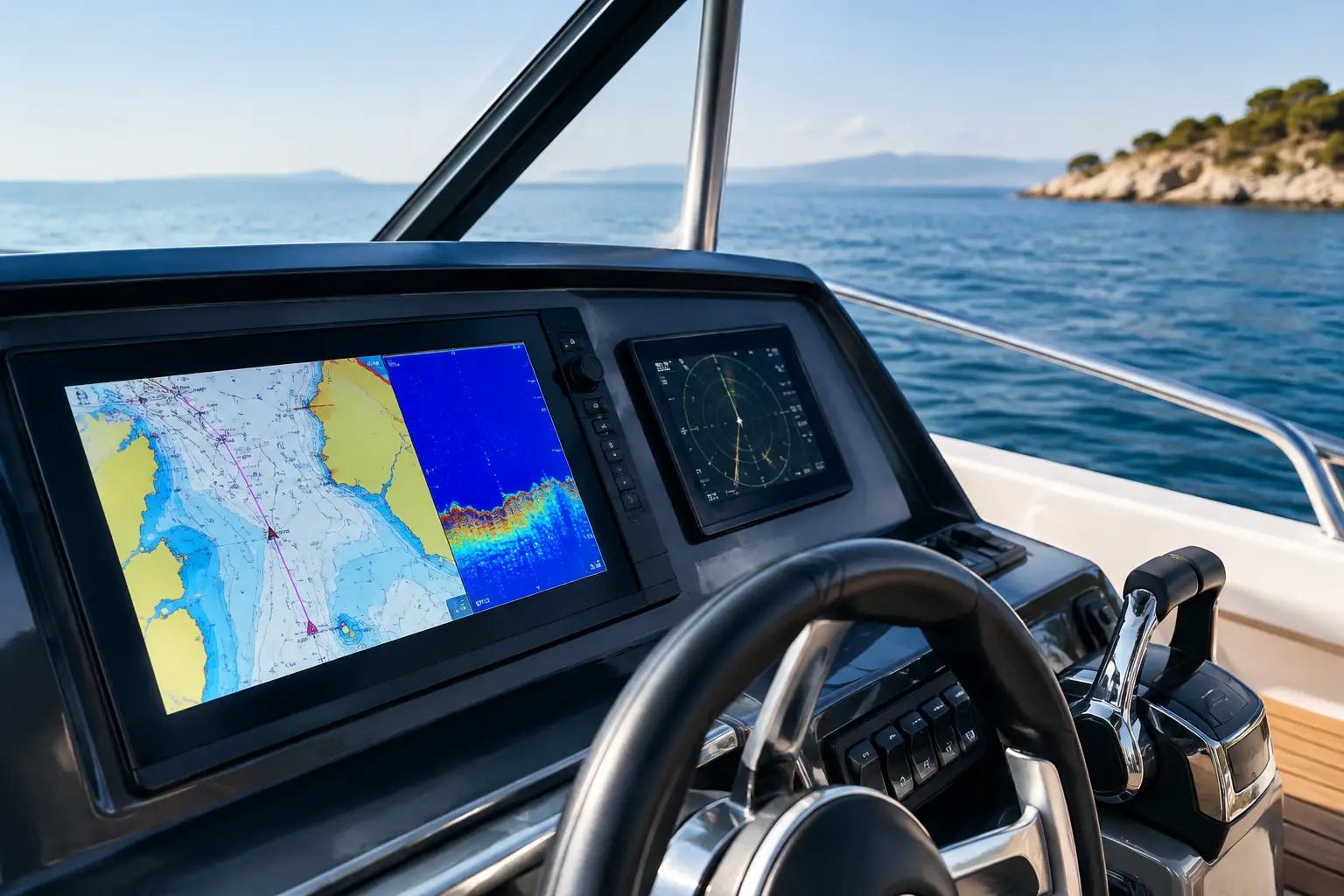
When the chart on the screen lags, vessel position is inaccurate, or data from sonar and radar do not display properly, the problem is not just navigation. Such situations affect maneuvering safety, the captain's decisions, and vessel availability. Garmin plotters can be the core of the navigation system, but only if properly selected, connected, and configured for the actual operating conditions of your vessel.
On a sailboat spending weekends between islands, the requirements differ from those on a motorboat used for longer routes, a charter catamaran, or a yacht with a professional crew. Screen size is important, but it does not alone determine system functionality. Before selection, existing electronics, network architecture, available space on the helm, and data you want to see during navigation must be reviewed.
What a Garmin Plotter Must Do on Your Vessel
A plotter is more than just a chart display device. Depending on system implementation, it can unify GPS position, electronic charts, AIS targets, depth, sea temperature, engine data, wind, radar, camera, and control of certain connected devices. Its value lies not in the number of functions on the specification sheet, but in whether it shows the crew the correct data, at the right place, without unreliable interruptions.
For a smaller recreational vessel, often a single well-placed multifunction display with quality charts and reliable depth readings suffices. For larger vessels or those sailing at night, in reduced visibility, or on longer routes, two workstations, radar display, AIS, and network integration become justified requirements. Charter vessels require special attention to simple user interface, equipment protection, and the possibility of rapid diagnostics between guest or crew shifts.
It is important to distinguish navigational comfort from functions that truly increase situational awareness. For example, an AIS receiver or transceiver displays other AIS-equipped vessels but does not replace visual lookout or radar. Sonar provides useful depth and bottom structure data, but display quality directly depends on the chosen transducer, its hull position, and sea conditions.
Choosing a Garmin Plotter Begins with System Review
The right recommendation does not start by asking which model is currently available. It starts with a technical inspection of the vessel and defining the intended use. It is necessary to determine which navigation devices are already installed, the condition of cables and connectors, whether an NMEA 2000 network exists, how power supply is implemented, and which data the system needs to exchange.
Screen, Mounting, and Visibility
Screen diagonal must correspond to the distance from which the device is operated, available console space, and the amount of data to be displayed simultaneously. Too small a screen may limit the ability to monitor radar, AIS, depth, and engine parameters along with charts. Conversely, too large a screen may require console modification, reduce instrument visibility, or cause issues with sun and water protection.
Mounting on a bracket facilitates access to the back of the device and subsequent servicing, while flush mounting offers a tidier appearance and better protection in the cockpit. Both options require proper sealing, mechanical fixing, and space for cable bend radius. The screen must remain readable in direct sunlight, and controls operable with wet hands and under vibration conditions.
Charts, GPS, and Navigation Data
Quality cartography is useful only if regularly updated and if the crew understands its limitations. An electronic chart is not a substitute for route planning, local notices to mariners, or weather assessment. The Garmin plotter should be configured to clearly display critical information for the route, shoals, safety contours, and alarms, avoiding unnecessary screen clutter.
The built-in GPS receiver is sufficient for many installations. However, device placement inside cabins, metal superstructures, carbon components, or other interference sources sometimes justify an external GPS antenna. For systems with multiple displays and instruments, it must be ensured all devices use a consistent source of position, time, and course.
NMEA 2000, Engines, and Existing Equipment
The NMEA 2000 network enables data exchange between the plotter, wind instruments, depth sensors, AIS, autopilot, engines, and other compatible devices. However, the network does not become reliable by merely connecting T-connectors. Proper backbone topology, suitable termination resistors, separate drops to devices, voltage and load checks, and quality cables and connectors are necessary.
Older vessels often feature a mix of NMEA 0183 devices, unlabeled wiring, and retrofitted components. Such a system can be integrated but requires a methodical approach. Before replacing the plotter, each existing signal must be identified: GPS, heading, depth, AIS, engine data, VHF DSC, and autopilot. Only then can it be decided if the existing device should remain, connect via converters, or be replaced.
Special attention is warranted in autopilot integration. The plotter can transmit navigation data to the autopilot, but the captain must still monitor route, obstacles, traffic, and engine operation. Improper compass calibration, incorrectly defined heading source, or network communication interruptions can cause behavior misinterpreted by the crew as a plotter malfunction.
Radar, AIS, and Sonar Are Not Accessories Without Context
Radar is useful for navigation at night, rain, fog, and in busy traffic areas but requires proper antenna placement, secure mount, correct power supply, and precise configuration. Too low installation may create shadowed areas, while too high installation affects service practicality and increases cable runs. After installation, radar picture alignment with chart, bow direction, and real-condition operation must be verified.
AIS adds a valuable layer of information, especially on commercial traffic routes. It must be checked if it is receiver-only or transceiver, the type of VHF antenna system, and how antenna sharing with VHF devices will be resolved. For transceivers, correct MMSI data, GPS source, and antenna installation are critical.
For fishing, anchoring in coves, and depth monitoring, a suitable transducer is important. Thru-hull, stern, or internal installations are selected based on hull material and shape, vessel speed, and desired type of reading. A transducer in turbulence zones may provide unstable data when it is most needed. Therefore, its installation is not a trivial task when replacing the navigation display.
Power Supply and Protection Determine Reliability
Navigation electronics depend on stable power. Voltage drops during engine start, poor grounding, corroded fuses, or a shared feed with heavy loads can cause device restarts, network interruptions, or intermittent faults difficult to diagnose later.
The Garmin plotter should have properly dimensioned wiring, adequate fuses, quality connections, and clearly marked circuit breakers in the distribution panel. On vessels with modernized battery systems, DC-DC chargers, inverters, or LiFePO4 banks, behavior under all operating modes – charging, loading, and power source switching – must be checked.
Protection against moisture, UV radiation, vibration, and electromagnetic interference should also be planned. Neat installation is not just aesthetic; it allows clear servicing, reduces error risk, and facilitates future system expansion.
Installation, Configuration, and Commissioning
After physical installation comes the phase often decisive whether the system will truly function as a whole. Data sources must be configured, software updated as necessary, alarms set, network communication checked, and connected sensors calibrated. For radar, autopilot, sonar, and engine data, verification does not end in the marina – some testing must be done at sea.
Commissioning includes verifying GPS position, charts, AIS targets, depth, heading, radar overlay, and communication with other devices. The crew must be handed the system with clear explanations of basic functions, alarm handling, and maintenance procedures. Equally important is documenting the installation so future service or upgrading is controlled and not guesswork-based.
UnLucky conducts compatibility checks, system design, installation and integration, configuration, sea trials, and subsequent diagnostics and technical support for navigation systems. If you plan a new Garmin plotter or are solving problems with an existing system, send an inquiry with vessel details, existing electronics, and usage mode. Safe navigation does not rely on luck. Because Luck Has Nothing to Do With It.